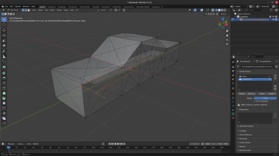
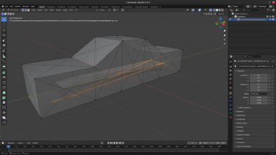
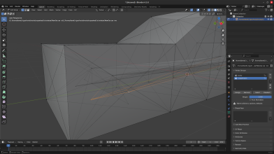
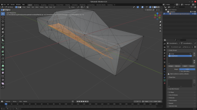
Basic Car Tutorial

devel

Modem
This is a basic car tutorial that should result in a fully functioning, nondeformable car that may or may not drive how you want it to. If not, you can optimize it to your liking afterwards with your new skills. It won't be a very realistic car, as it'll have a simple solid beam rear suspension and no front suspension for maximum simplicity, making use of snodes for the rear
Note that I will refer to vertices as nodes and edges as beams for simplicity's sake
Requirements:
Blender (latest version is recommended for this tutorial, 4.5 at the time of writing)
- N/B import/export plugin
- OGRE Mesh import/export plugin (If you're going to make a mesh for it)
Blank Truck File
Any text editor
Chapter 1: Setup
Open Blender, then configure your first-time preferences if this is your first time.
On this screen, choose General:
Screenshot from 2025-08-05 16-58-51.png
Follow these steps to install the required plugins
Then, press A and X to delete all of the objects
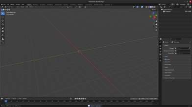
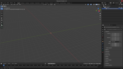
Your screen should look a little something like this:
image.png
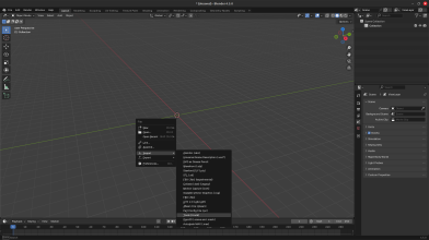
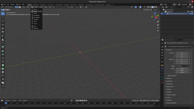
Then, press F4, then hover over Import, then if you installed the N/B plugin correctly, click Truck (.truck)
image-1.png
Navigate to where you downloaded NewTruck.truck (most likely your downloads folder) and open it
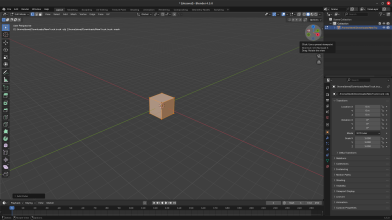
You won't see anything except for an extra object in the right side object list. This is normal.
image-2.png
 
Chapter 2: Making the main body
Press Tab to go into edit mode, then click Add on the top bar, then Cube:
image-3.png
Press alt+Z to go into wireframe mode. This will be useful later
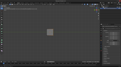
Click on the dark red circle on the top right gizmo to rotate your camera to the right of the cube in orthographic view:
image-4.png
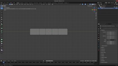
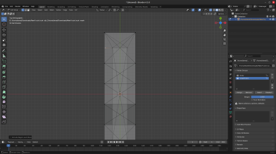
Click and drag your mouse cursor over the two right (front) nodes to select them:
image-5.png
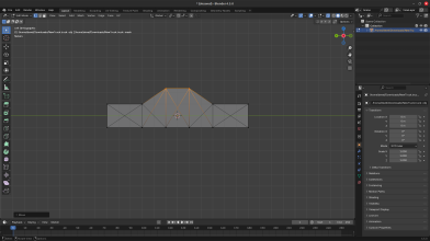
Press E to extrude them and drag your mouse to the right about 2 squares, then click to finalize the extrusion. Press E again, but drag your mouse right about 3 squares this time.
Now, do this again, but for the opposite side. Your screen should look like this:
image-6.png
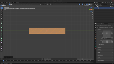
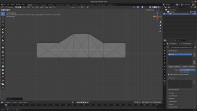
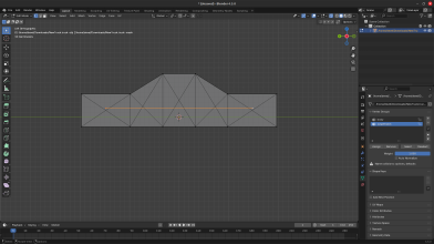
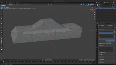
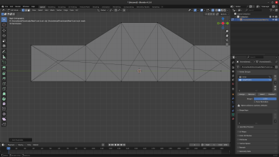
Press A to select all nodes and ctrl+t to triangulate all faces. It should look like this:
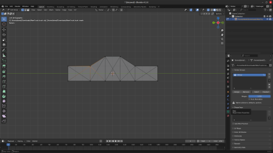
image-8.png
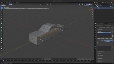
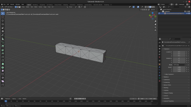
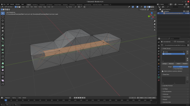
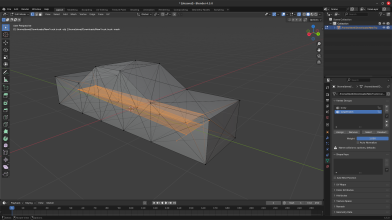
To add more triangulation to make the vehicle stronger, select two unconnected nodes by shift clicking them and pressing F to join them. You can press alt+z again to exit wireframe mode. Rotate the camera by pressing your middle mouse button and dragging, or clicking and dragging the top right gizmo.
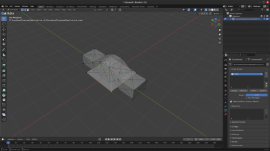
The result should look like this:
image-9.png
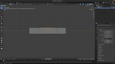
Press the dark red circle on the top right gizmo again, alt+z to go into wireframe mode, and click and drag your mouse over the two middle top nodes:
image-7.png
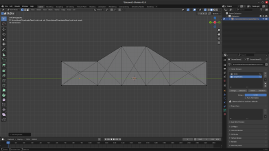
Then press G to move them, Z to restrict them on the Z-axis, and move your mouse upwards about 1 and a quarter to 1 and a half squares:
image-10.png
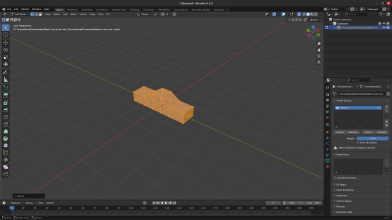
If you rotate the camera a bit, you'll realize the car is horribly thin. To fix this, press A to select all nodes, S to scale, and X to restrict scaling to the x-axis. Drag your mouse outwards to a desirable proportion:
image-13.png
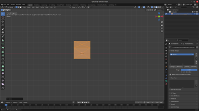
Now, when you spawn the car in Rigs of Rods, it'll be massive. So to fix this, click on the blue Z on the top right gizmo to go to the top orthographic view, press A to select all and S to scale. Drag your mouse inwards to the middle to scale down until it's about 4 to 5 squares (meters) long:
image-14.png
Now you're done with the body! But before moving on to the suspension, it'll be helpful to add it to a vertex group
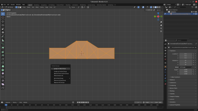
Press A to select all nodes, and ctrl+g to open the vertex group menu. Press Assign to new group.
image-11.png
Click the green Data button on the right sidebar:
image-12.png
You'll see your newly created group, and if you did it right, pressing Select and Deselect will select all the nodes and deselect all of them.
You can rename it to something like body, mainbody, or whatever else you have in mind
Keep the Data tab open, as you'll need it later
 
Chapter 3: Making the rear suspension
Click Add in the top bar and click Plane
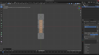
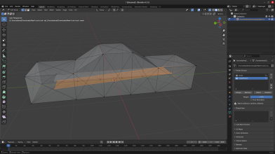
Immediately press ctrl+t and connect the remaining 2 nodes by shift clicking them and pressing f:
image-15.png
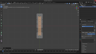
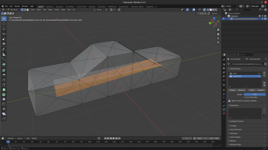
Resize the plane by shift clicking its nodes, then press S to scale, X to restrict to x-axis, and drag your mouse inwards to make it thinner:
image-16.png
Then resize it to make it longer by pressing Y instead of X to restrict along the y-axis, and drag out to make the wheelbase about this big:
image-17.png
Make sure the nodes are still selected, go to left orthographic view by clicking the red circle in the top right gizmo.
Move the nodes by pressing G and restrain them on the z-axis by pressing Z, then drag upwards. This will be how far up the suspension can travel:
image-18.png
Add them to another vertex group by pressing ctrl+g, selecting Assign to new group, and renaming it to something like suspension in the Data tab.
image-19.png
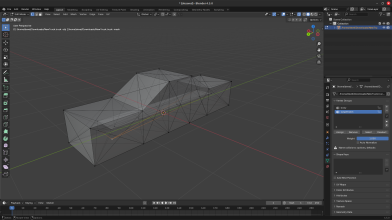
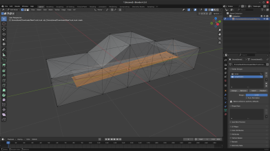
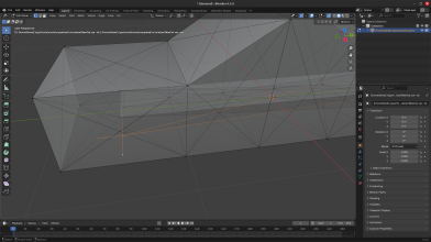
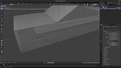
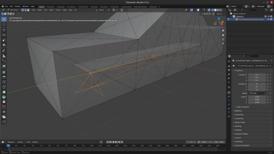
Connect the nodes of the suspension to the body by shift clicking a suspension and body node, and pressing F. Do this to brace the suspension so that it doesn't move any direction other than upwards. The connections should look like this:
image-20.png
Now for the moving part.
Click and drag over the rear suspension nodes, press shift+d to duplicate them, Z to restrain to the z-axis, and drag your mouse down until the nodes are at the green line:
image-21.png
Keep those nodes connected, but shift click the front suspension nodes and press F:
image-24.png
image-25.png
Then press ctrl+t and connect the remaining 2 nodes by shift clicking them and pressing F:
image-26.png
Click on a bottom side suspension node, press E to extrude, X to restrain to x-axis click the blue Z on the top right gizmo, and drag your mouse out until the new node is flush with the side of the car or slightly inside:
image-27.png
image-28.png
Do the same for the other side.
image-29.png
And now you're done!... with the rear suspension. Now for the front
 
Last edited:
Chapter 4: Making the front suspension
Select the 2 front suspension nodes, duplicate them, and move them to the green line the same way you did to the rear suspension:
image-30.png
Connect the bottom front suspension nodes to the top rear suspension nodes the same way you connected the rear to the front:
image-31.png
Extrude the new nodes out to the side of the car just like the rear ones:
image-32.png
Now, you're going to have to make the wheel holders so you can steer. This will be the main difference between the front and rear suspension.
Select a middle bottom node of the front suspension, and extrude it forwards about this much by pressing Y after you extrude with E:
image-40.png
Do the same, but backwards:
image-41.png
Now, connect these new nodes together along with the top node, except for the 2 side nodes and the outer node:
image-42.png
Connect all of these nodes together by shift clicking them and pressing F, one at a time:
image-43.png
Also make sure you connected these nodes:
image-44.png
Do the same to the other side:
image-45.png
Yay, the front suspension is done!
Now, the technical bits
Chapter 4.5: Exporting
Press A to select all, F4 to bring up the file menu, hover over Export, and click Truck (.truck). Navigate to your mods folder. On Windows, this will be in Documents/Rigs of Rods/mods. On Linux, this will be in ~/.rigsofrods/mods. I recommend making an "unpacked" folder in the mods folder to make future projects easier to make and edit. In the unpacked folder, add another folder "tutorialcar" or whatever you want to call it and export to there. When you go there in your file browser, there will be no file extension, so just add .truck (or .car if you want to be fancy).
Keep Blender open for the text editing.
 
Chapter 5: Text editing
Open the file with any text editor. The first line will be the name that you see in the vehicle selector. Rename it if you want. The next few lines will be credits. The first word will always be "author", the second will be what that person did (use underscores instead of spaces), the third is their user ID (if you don't know yours just use -1), and the last is their username. You can add some or delete some, I have just one credit to me who did everything:
image-39.png
You can delete the next section, forwardcommands, as it only really applies to trailers
The engine section is mostly preference, but I recommend you reduce the torque (3rd value) to 200-500 as the default 6000 is for big trucks
You can read the docs section [here](https://docs.rigsofrods.org/vehicle-creation/fileformat-truck/#engine)
Also add an engoption section under it to tune the inertia, shifting, and other values
For this, you should reduce the inertia (1st value) to 0.01 to 0.05, and the type (2nd) value to c
If you want, you can add a turbo with [engturbo](https://docs.rigsofrods.org/vehicle-creation/fileformat-truck/#engturbo)
You don't need to mess with nodes or beams, as those were handled by Blender and the exporter
However, you should add "submesh" under the beams section, scroll all the way to the bottom, and you'll find the sneaky cab section. Cut and paste it to be under submesh:
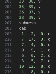
image-46.png
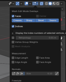
Here, you'll need Blender again. While in edit mode (allows you to select individual nodes), click on the little square on the top bar:
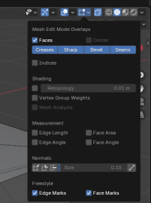
image-47.png
And check indices:
image-48.png
The camera section is pretty simple. All you need are three values, center node, back, and left.
For me the section looks like this:
image-49.png
For you, it should be the same, but just to make sure, go back into Blender, and select these nodes:
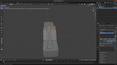
image-50.png
You can see that the nodes are on the roof, with 1 being in front, 3 being behind it, and 7 being to the left of 3. If your nodes are different than mine, fill them in with your correct ones.
The cinecam section can be ignored for now (but not deleted) as extra cameras are not needed. However, if you want, you can try adding one using the docs here
The wheels section looks pretty complicated, but it gets pretty easy when you understand the docs section for it
The values you need to change are the radius, nodes, rigidity node, wheel braking, wheel drive, and reference arm node
If you exactly followed these instructions, the radius should be 0.26 as it's a pretty good size, not too big, not too small. Keep the rays (3rd value) the same, as it's already smooth enough with 12 sides, and raising it will probably only give a performance loss. The 2 node ID's, you'll definitely need Blender for. Go back into Blender, and select these nodes by shift clicking them:
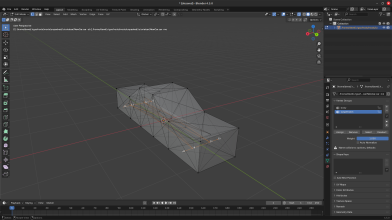
image-51.png
image-52.png
The order doesn't matter on the individual line level. For me this is what my wheel section looks like:
image-53.png
You should be able match my node numbers in the file to where they are graphically in Blender. If you selected those same nodes, you should be able to replace my node values with what you see in Blender.
The next value is only for the rear wheels, I'll tell you right away that you should put 9999 for the front wheels. In Blender, select these nodes:
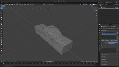
image-54.png
Again, you should be able to deduce that the rigidity node for the left is 29, and the rigidity node for the right is 28. Replace these numbers with what you've selected in Blender.
The next value is simple. For the rear wheels, it should be 1 as they have a footbrake and handbrake, but for the front wheels, you should do 4 as they would have a footbrake, but no handbrake, or you could do 1 if you want
The next value is preference. If you want a FWD car, make this value 0 for the rear wheels and 1 for the front. If you want a RWD car, do the opposite. If you want AWD, set them all to 1. The next value you'll need Blender for again.
Select these nodes:
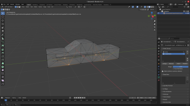
image-55.png
For my front right wheel, this value is 8, the front left is 10, rear right is 16, rear left is 18. Replace these values with the node numbers you selected.
You don't need to mess with the next few values, but you can try some different ones after you're done
The shocks section is pretty simple, as you can use this template and only change a few values:
shocks
;critical damping=2*sqrt(mass*spring)
;id1, id2, spring, damping, shortbound, longbound, precomp, options
26, 29, 200000, 10000, 0, 0.3, 1.0
27, 28, 200000, 10000, 0, 0.3, 1.0
There's only 2 shocks as the rear suspension needs 2 and the front needs none. In Blender, select these nodes:
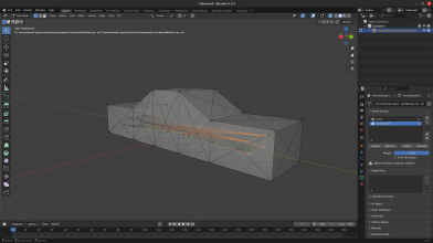
image-56.png
You can see that I had the top node as the first value and bottom node as the second value, but you can reverse them. Replace my node numbers with yours. You can reduce the spring if it's too stiff for your liking.
The next section, hydros, is what gives you steering. Here's a starting template:
hydros
;node1, node2, factor, options
35, 37, -0.2
35, 36, 0.2
34, 39, 0.2
34, 38, -0.2
Select these nodes in Blender:
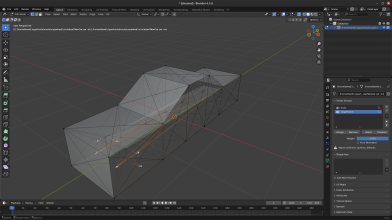
image-57.png
You can see that the outer nodes have 2 hydros connected to them. Replace the outer node values with ones that you have in Blender. The second values are very important. If you don't have them in the correct order, you could break something or not be able to steer, or both. Make sure that the node values you selected in Blender exactly subsitute the ones that I have.
And now you're done with the basic car! If you want to check out the other sections, read about them in the docs, as they aren't necessary for making this car. Perhaps I'll make another thread or few showcasing these features.
 
Last edited:
Back
Top